
Cooling system - expansion tank installed
15 posts
• Page 1 of 1
![]() Post by: leifanten » Fri Oct 08, 2010 11:53 pm
Post by: leifanten » Fri Oct 08, 2010 11:53 pm
chaps,
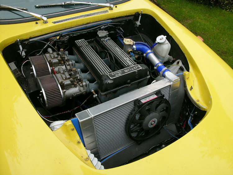
I just wanted to show how I installed an expansion tank to my cooling system. What you do not see is the 1/2'' hose running to a t-junction inserted in the return side of the hose that runs from the interior heater. So far so good. All I need now is to install an air bleed valve to the thermostat housing. To make the t-junction I used some bits and pieces from Ace hardware. I got the tank from ebay. I can post a link if interest.
I just wanted to show how I installed an expansion tank to my cooling system. What you do not see is the 1/2'' hose running to a t-junction inserted in the return side of the hose that runs from the interior heater. So far so good. All I need now is to install an air bleed valve to the thermostat housing. To make the t-junction I used some bits and pieces from Ace hardware. I got the tank from ebay. I can post a link if interest.
- Attachments
-
 Viewed 4935 times")
Leif
1968 +2 Wedgewood blue
Houston, TX
1968 +2 Wedgewood blue
Houston, TX
- leifanten
- Second Gear

- Posts: 152
- Joined: 28 Sep 2009
![]() Post by: elansprint71 » Mon Oct 11, 2010 4:57 pm
Post by: elansprint71 » Mon Oct 11, 2010 4:57 pm
billwill wrote:How will any air that accumulates in the thermostat housing be transferred to the tank, where it will do less harm.
I was thinking just the same thing. I don't think that your expansion tank is adding much value.
If you look in the archives you will see what other folks (myself included) have done to address this problem and it is worth saying that very many folks do not have the problem.
Cheers,
Pete.
http://www.petetaylor.org.uk
LOTUS ELAN flickr GROUP: https://www.flickr.com/groups/2515899@N20
flickr: http://www.flickr.com/photos/16096573@N02/sets/72157624226380576/
https://www.flickr.com/photos/16096573@N02/
Pete.
http://www.petetaylor.org.uk
LOTUS ELAN flickr GROUP: https://www.flickr.com/groups/2515899@N20
flickr: http://www.flickr.com/photos/16096573@N02/sets/72157624226380576/
https://www.flickr.com/photos/16096573@N02/
-

elansprint71 - Coveted Fifth Gear

- Posts: 4437
- Joined: 16 Sep 2003

![]() Post by: leifanten » Mon Oct 11, 2010 8:27 pm
Post by: leifanten » Mon Oct 11, 2010 8:27 pm
Bill: You are right, and I have a small brass 3/8 NPT air bleed valve en route that I will install in the thermostat housing that will round off the modification to address this particular issue.
Pete: I am aware that for most folks in the rest of the western world do not have to cope with the constant 35-40 deg C summers that we have in Houston overheating is not an issue. Here, however, it is a real issue.
What I have installed is basically what more modern cars has, where the expansion tank is a pressurised container that has one line entering the bottom of the tank going to the suction side of the water pump and one line from the top of the tank to the top of the radiator, where it vents through the original over pressure outlet (through a modified rad cap.
It remains to be seen what difference it makes, but I experimented with a "high fill point" pipe sub installed in the top radiator hose that bled into a catch tank. The car held its own in most temperatures, but as soon as it blew out a bit of fluid into the catch tank, the operating temperature went from 85 to 95, so I figured that if I was able to create a pressure buffer to not lose that fluid, I would be able to keep it at 85. Time will show. It at least gave me something to play with a couple of evenings.
Pete: I am aware that for most folks in the rest of the western world do not have to cope with the constant 35-40 deg C
What I have installed is basically what more modern cars has, where the expansion tank is a pressurised container that has one line entering the bottom of the tank going to the suction side of the water pump and one line from the top of the tank to the top of the radiator, where it vents through the original over pressure outlet (through a modified rad cap.
It remains to be seen what difference it makes, but I experimented with a "high fill point" pipe sub installed in the top radiator hose that bled into a catch tank. The car held its own in most temperatures, but as soon as it blew out a bit of fluid into the catch tank, the operating temperature went from 85 to 95, so I figured that if I was able to create a pressure buffer to not lose that fluid, I would be able to keep it at 85. Time will show. It at least gave me something to play with a couple of evenings.
Leif
1968 +2 Wedgewood blue
Houston, TX
1968 +2 Wedgewood blue
Houston, TX
- leifanten
- Second Gear
- Posts: 152
- Joined: 28 Sep 2009
![]() Post by: elansprint71 » Tue Oct 12, 2010 7:40 am
Post by: elansprint71 » Tue Oct 12, 2010 7:40 am
Leif,
I understand the theory! I had problems with air-locking in the system- I believe that the highest point in the system is in a heater hose, somewhere behind the dash (not exactly convenient to bleed!). This is what I came up with:
The cap on the thermo-housing is not a pressure cap, so air goes into the bottom of the expansion tank and stays in there.
No probs with cooling, thanks to the rad, but still, very occasionally, get a build-up of air in the heater.
Last edited by elansprint71 on Thu Oct 14, 2010 1:26 pm, edited 1 time in total.
Cheers,
Pete.
http://www.petetaylor.org.uk
LOTUS ELAN flickr GROUP: https://www.flickr.com/groups/2515899@N20
flickr: http://www.flickr.com/photos/16096573@N02/sets/72157624226380576/
https://www.flickr.com/photos/16096573@N02/
Pete.
http://www.petetaylor.org.uk
LOTUS ELAN flickr GROUP: https://www.flickr.com/groups/2515899@N20
flickr: http://www.flickr.com/photos/16096573@N02/sets/72157624226380576/
https://www.flickr.com/photos/16096573@N02/
-
elansprint71 - Coveted Fifth Gear
- Posts: 4437
- Joined: 16 Sep 2003
![]() Post by: kstrutt11 » Tue Oct 12, 2010 9:42 am
Post by: kstrutt11 » Tue Oct 12, 2010 9:42 am
I'm in the process of a very similar conversion on my +2, I'm using a TR7 header tank which will put all the extra coolant above head level and the thermostat housing as shown in the last picture. My main reason is to give a bit more coolant volume and a bit more time to react to any leaks before overheating.
Kevin.
Kevin.
- kstrutt11
- Third Gear

- Posts: 427
- Joined: 27 Jun 2007
![]() Post by: summerinmaine » Tue Oct 12, 2010 2:51 pm
Post by: summerinmaine » Tue Oct 12, 2010 2:51 pm
elansprint71 wrote:Leif,
I understand the theory! I had problems with air-locking in the system- I believe that the highest point in the system is in a heater hose, somewhere behind the dash (not exactly convenient to bleed!).
I've heard this as well. While I have the car apart, I plan to install a manual bleed valve near the heater, so that I can occasionally purge the system. Of course, if the high point is in the heater core itself, I might not bother.
But when changing coolant, I use a pressure system and have never had any problems with air. The pressure of the coolant input seems to flush the air out.
Jim
Temporarily Elan-less
Temporarily Elan-less
-

summerinmaine - Fourth Gear

- Posts: 689
- Joined: 22 Sep 2003

![]() Post by: summerinmaine » Tue Oct 12, 2010 2:55 pm
Post by: summerinmaine » Tue Oct 12, 2010 2:55 pm
Has anyone tried to park their Elan nose-up on an incline, run the car for a bit and then purge? Or does the heater hose dropping down to the engine form an air trap?
Jim
Temporarily Elan-less
Temporarily Elan-less
-
summerinmaine - Fourth Gear
- Posts: 689
- Joined: 22 Sep 2003
![]() Post by: c42 » Tue Oct 12, 2010 9:07 pm
Post by: c42 » Tue Oct 12, 2010 9:07 pm
Some years ago when I used to race rear engine water cooled cars with a front mounted radiator ,air locks and air build up in the head were cured by using either a swirl pot or high mounted header tank with a bleed pipe running from the top of the thermostat housing to the top of the expansion tank. The flow was restricted by only opening the bleed hole up to about 2.5mm; the outlet from the bottom of the expansion tank was teed into the suction side of the water pump so that there was a constant flow from the thermostat housing into the expansion tank removing any air with it and then back to the system but with the restriction not too much flow to bypass the cooling system.
Hope this helps.
Regards
John
Hope this helps.
Regards
John
-

c42 - Third Gear
- Posts: 333
- Joined: 10 Sep 2009

![]() Post by: bcmc33 » Tue Oct 12, 2010 9:19 pm
Post by: bcmc33 » Tue Oct 12, 2010 9:19 pm
summerinmaine wrote:Has anyone tried to park their Elan nose-up on an incline, run the car for a bit and then purge?
We tried this some years ago, and if it worked to start with - it was not maintained. A bit of fun, but a waste of time was the conclusion.
From my calculations the Ford/Cliveyboy thermo housing is just about the highest point of the cooling system - so this is the route to go, (IMHO).
However, there is some mileage to be acieved in the overflow/recovery system - something where I've yet to get a fully satisfactory result - that's why I may take a close look at Peter's idea.
Brian Clarke
(1972 Sprint 5 EFI)
Growing old is mandatory..........Growing up is optional
(1972 Sprint 5 EFI)
Growing old is mandatory..........Growing up is optional
-

bcmc33 - Coveted Fifth Gear
- Posts: 1825
- Joined: 10 Apr 2006
![]() Post by: dlbarnes1 » Wed Oct 13, 2010 9:46 pm
Post by: dlbarnes1 » Wed Oct 13, 2010 9:46 pm
I located an expansion tank in the top hose in conjunction with the installation of a cross flow radiator. This takes care of the venting concern.
The fill level in the tank is at the top of the outlet connection to the radiator. The expansion volume is the remaining volume in the tank plus the volume of the thermostat housing and hose connection to the tank. With this expansion volume, there has been no overflow to the recovery bottle with the maximum coolant temperature being 195 degrees F (the temperature where the electric fan starts).
I think the optimum arrangement for an expansion tank, generally speaking, is a bottom connection to a tee at the inlet to the water pump. But, it seems to me, this arrangement doesn't easily, or neatly, lend itself to the Elan configuration.
Dave - 72 Sprint DHC
- Attachments
-
-
 Viewed 4899 times")
 Viewed 4896 times")
- dlbarnes1
- Second Gear
- Posts: 139
- Joined: 22 Sep 2003
![]() Post by: leifanten » Thu Oct 14, 2010 1:04 am
Post by: leifanten » Thu Oct 14, 2010 1:04 am
Pete, Dave,
I think what we have done achieves the same, although I have not gone all in with the aluminum radiator. I did, however, connect to the inlet of the water pump as mentioned by Pete. I did this by hot-tapping through a brass t-joint at the inlet of the pump (in the hose from the outlet of the heater). I wanted to keep a "near to orignial" appearance, hence the matt black expansion tank. The remaining item is to install a small bleeder valve threaded into the thermostat housing.
I think what we have done achieves the same, although I have not gone all in with the aluminum radiator. I did, however, connect to the inlet of the water pump as mentioned by Pete. I did this by hot-tapping through a brass t-joint at the inlet of the pump (in the hose from the outlet of the heater). I wanted to keep a "near to orignial" appearance, hence the matt black expansion tank. The remaining item is to install a small bleeder valve threaded into the thermostat housing.
Leif
1968 +2 Wedgewood blue
Houston, TX
1968 +2 Wedgewood blue
Houston, TX
- leifanten
- Second Gear
- Posts: 152
- Joined: 28 Sep 2009
![]() Post by: gerrym » Thu Oct 14, 2010 6:28 am
Post by: gerrym » Thu Oct 14, 2010 6:28 am
Leif, Dave. No need for a recovery bottle with this system if properly sized. The expansion tank has a gas filled head space into which the liquid expands as it heats up. I can do the calculation if anyone is interested for various temperature and mixture strengths. The expansion tank (if it has a continuous inlet bleed and return to the suction side of the pump) will act as a swirl pot. Most of the properly designed ones have internal baffling to ensure this happens in an efficient manner.
By the way, a coolant recovery bottle is a very good way of continuously topping up the system with nice corrosion inducing oxygen (from the air).
Regards
Gerry
PS, calcs generally as here:-( c is cold, h is hot)
Expansion Volume (Ve)= Cold Volume (Vc) * (ratio of specific gravities (SGc/SGh)-1)
for a 40% by weight MEG mixture SGc= 1.058 @ 50F and SGh=0.983 @ 250F
so Ve= Vc*0.07. For 60% by weight MEG mixture, Ve=Vc*0.08
some numbers to illustrate. For a cooling system with a cold fill of 8 litres, the expansion volume required would be 8 * 0.08 =0.64 litres. Any additional expansion beyond this is due to gas or air coming out of the system (out of solution or trapped during filling). Note there is a little conservatism here as as not really necessary / possible to run system at 250F.
- gerrym
- Fourth Gear
- Posts: 894
- Joined: 25 Jun 2006
![]() Post by: summerinmaine » Thu Oct 14, 2010 2:27 pm
Post by: summerinmaine » Thu Oct 14, 2010 2:27 pm
dlbarnes1 wrote:I located an expansion tank in the top hose in conjunction with the installation of a cross flow radiator. This takes care of the venting concern.
The fill level in the tank is at the top of the outlet connection to the radiator. The expansion volume is the remaining volume in the tank plus the volume of the thermostat housing and hose connection to the tank. With this expansion volume, there has been no overflow to the recovery bottle with the maximum coolant temperature being 195 degrees F (the temperature where the electric fan starts).
I think the optimum arrangement for an expansion tank, generally speaking, is a bottom connection to a tee at the inlet to the water pump. But, it seems to me, this arrangement doesn't easily, or neatly, lend itself to the Elan configuration.
Dave - 72 Sprint DHC
As I understand it, isn't this the way the 26R was set up with an expansion tank/swirl pot?
I've seen repros available for reasonable prices from some of the usual sources.
Jim
Temporarily Elan-less
Temporarily Elan-less
-
summerinmaine - Fourth Gear
- Posts: 689
- Joined: 22 Sep 2003
![]() Post by: stugilmour » Sat Oct 23, 2010 6:22 pm
Post by: stugilmour » Sat Oct 23, 2010 6:22 pm
leifanten wrote:chaps,
... I got the tank from eBay. I can post a link if interest.
Hi Leif. I tried PM'ing you to get the eBay link for the tank, but it didn't work. Could you post the seller link? Looks like a tidy fit, and the one I am considering using might be a bit large to fit in the same location you used.
thx
Stu
1969 Plus 2 Federal LHD
1969 Plus 2 Federal LHD
-

stugilmour - Coveted Fifth Gear
- Posts: 2063
- Joined: 03 Sep 2007

15 posts
• Page 1 of 1
Total Online:
Users browsing this forum: No registered users and 20 guests