
Electric light pods
21 posts
• Page 1 of 2 • 1, 2
![]() Post by: john.p.clegg » Mon Aug 04, 2008 12:55 pm
Post by: john.p.clegg » Mon Aug 04, 2008 12:55 pm
Hi all
Am now officially on the sick,so thought I'd spend some time spannering ready for the EFI,where to mount the swirl pot and pump.....only place there's room is the nose (no jokes about my Jewish ancestry) so while in there I'm goimg to move/tidy things and prepare for the electric lift motors....at first glance the drive pivot on the pod seems to move 4" (is that correct?) and the arm of the motor is 2" in radius.....am I lucky or am I missing something....I know some of you out there have done this....
also the motor mounts seem to align with the inner shell....looks like a flat ali plate will glass/bolt flush?
Other things to do while in the nose.....full width radiator.
John
P.S. excellent day at Woodvale-wouldn't miss it for the world
http://www.woodvale-rally.org.uk/02_what's_on.htm
-

john.p.clegg - Coveted Fifth Gear

- Posts: 5744
- Joined: 21 Sep 2003

![]() Post by: Jason1 » Mon Aug 04, 2008 7:49 pm
Post by: Jason1 » Mon Aug 04, 2008 7:49 pm
Hi
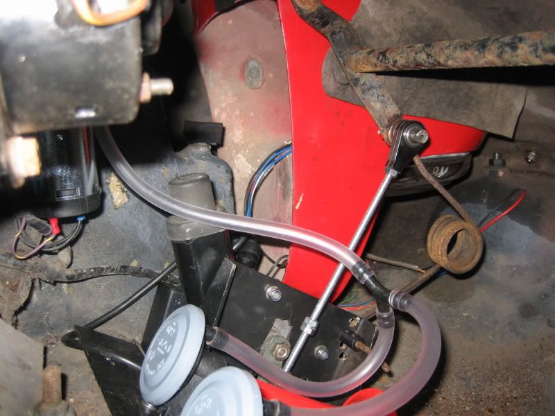
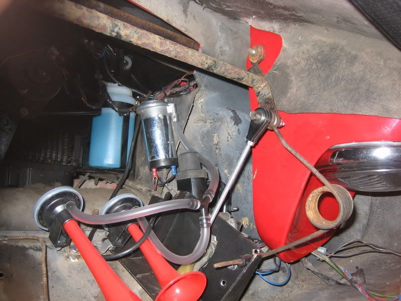
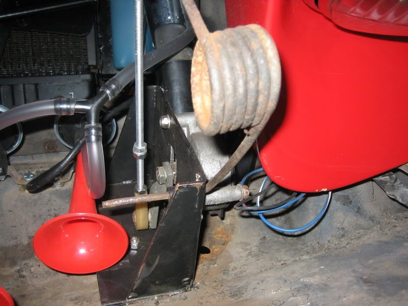
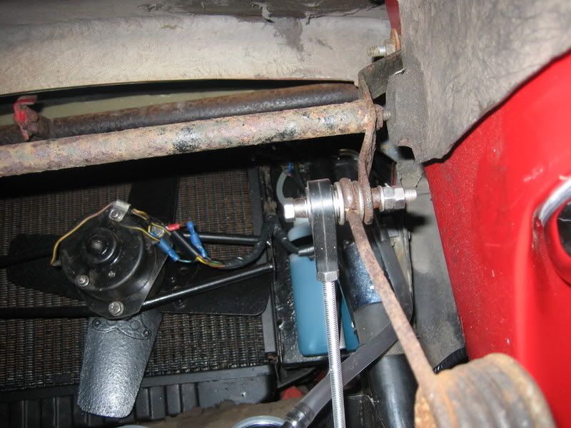
Just fitted electric motors last week, just tidying up the wiring and adjusting the rods now.
What motor are you using?
I used Mazda MX5 motors but if you use them as they are the pods will only come up half way and back down again. I had to lengthen the rotors, if you use Toyota Supra motors they have longer rotors.
See pics attached, look at the end of the rotors in comparison to the mounting holes, if you need any help with extra pics let me know.
Jason
- Attachments
-

- Supra motor
-

- MX5 motor


50/0951 1968 Wedgewood blue +2, 1990 Mini Cooper RSP
-

Jason1 - Coveted Fifth Gear
- Posts: 1554
- Joined: 03 Nov 2005

![]() Post by: john.p.clegg » Mon Aug 04, 2008 9:48 pm
Post by: john.p.clegg » Mon Aug 04, 2008 9:48 pm
Jason/Steve
Being greedy I hava a pair of each (1 1/2" and 2" arms),do you have a shot of them fitted as the idea I have is a flat plate fitted flush to the "inner wing" with the motors in the "recess",the rotors fitting through the plate inwards....sorry for the description but a picture is worth a thousand words...
John
-
john.p.clegg - Coveted Fifth Gear
- Posts: 5744
- Joined: 21 Sep 2003
![]() Post by: RotoFlexible » Tue Aug 05, 2008 11:26 am
Post by: RotoFlexible » Tue Aug 05, 2008 11:26 am
Rather than get or make different rotor arms, you can drill new holes in the pods, closer to or farther away from the pivot point as required. The procedure I used was something like this:
1. Determine the stroke of the motor (length of arm x 2).
2. Determine the stroke needed to move the pod at its current drive point. I fastened some string in the nose that intersected the drive location at full-open and full-closed, and marked those points.
3. Calculate the ratio between these two measurements. If the motor stroke is too long, you'll need to drill the new hole farther from the pivot; closer if too short.
I think - PLEASE CHECK BEFORE DRILLING! - that the required distance from the pivot is current distance * (motor-stroke / current-stroke).
You will need to drill the new holes, then align the shaft of the motor with the line drawn between the new hole in its open and closed position - use the string again.
I gave myself some wiggle room by using 1/4" nylon actuating rods, which can bend slightly under compression.
Andrew Bodge
'66 Elan S2 26/4869
I love the sound of a torque wrench in the morning. Sounds like... progress.
'66 Elan S2 26/4869
I love the sound of a torque wrench in the morning. Sounds like... progress.
-

RotoFlexible - Fourth Gear

- Posts: 679
- Joined: 01 Sep 2005
 Viewed 4944 times")
 Viewed 4947 times")
 Viewed 4945 times")
 Viewed 4949 times")
 Viewed 4954 times")
 Viewed 4989 times")
![]() Post by: john.p.clegg » Sat Aug 09, 2008 12:53 pm
Post by: john.p.clegg » Sat Aug 09, 2008 12:53 pm
Help Required
Well I'm about to fit the electric headlamp motors but have a problem....the wiring diagram has gone.....was stored in My Documents....done an archive search and found one marked Page E-1 but I'm sure there is another simpler one about?....Anyone help
John
P.S. could be toyota,mazda etc...5 wires
Well I'm about to fit the electric headlamp motors but have a problem....the wiring diagram has gone.....was stored in My Documents....done an archive search and found one marked Page E-1 but I'm sure there is another simpler one about?....Anyone help
John
P.S. could be toyota,mazda etc...5 wires
-
john.p.clegg - Coveted Fifth Gear
- Posts: 5744
- Joined: 21 Sep 2003
![]() Post by: Jason1 » Sat Aug 09, 2008 8:39 pm
Post by: Jason1 » Sat Aug 09, 2008 8:39 pm
Hi John
This is an easy one for me:
Yellow = Down
Red = Up
White/Red = Permanent live
Black = Earth
Green = You do not need this one
The red and yellow you can use as up or down its up to you, wire the black to the battery earth and the White/red to the live on a battery, then touch the yellow wire to the battery live and the motor will turn half a turn. Take the yellow off of the live and touch the red wire and the motor will turn the other half a turn.
I have tested these motors so many times I can do it in my sleep.
Jason
50/0951 1968 Wedgewood blue +2, 1990 Mini Cooper RSP
-
Jason1 - Coveted Fifth Gear
- Posts: 1554
- Joined: 03 Nov 2005
 Viewed 5013 times")
 Viewed 4992 times")

![]() Post by: john.p.clegg » Sun Aug 10, 2008 2:59 pm
Post by: john.p.clegg » Sun Aug 10, 2008 2:59 pm
Jason/Sadlotus
Many thanks,am still struggling,have five wires,two go into the motor and permenantly turn it when 12v applied,the other three go into a circular switchbox,green common ,blue and yellow via diodes to contact plate,both with off segments 180 opposite....there seems to be another switch at the bottom of the motor drive but cannot figure out if/how it is wired???
I have tried wiring motor via the circular switchbox but the inertia allows it to pass the off segments???
Any help gratefully recieved
John
-
john.p.clegg - Coveted Fifth Gear
- Posts: 5744
- Joined: 21 Sep 2003
![]() Post by: john.p.clegg » Sun Aug 10, 2008 3:30 pm
Post by: john.p.clegg » Sun Aug 10, 2008 3:30 pm
....Have just got it to work...in a fashion...live 12v to red/white,green to black/white,earth to yellow-half turn,earth to blue-half turn.......without any load it keeps on spinning.....with a light load seems to do the job???
John
Any suggestions?
John
Any suggestions?
-
john.p.clegg - Coveted Fifth Gear
- Posts: 5744
- Joined: 21 Sep 2003
![]() Post by: Matt » Mon Aug 11, 2008 11:07 am
Post by: Matt » Mon Aug 11, 2008 11:07 am
I've have my Single toyota supra motor setup running now for a few years and it's has never failed I use a 2.2ohm ceramic wire wound resister to set my speed and a home made control box the does not need limit switches. you are best using a single motor and a s130 type balance bar in my opinion and one single pod spring to counter balance the pod weight and give it an strong pod up bias.
If anyone is a bit stuck just pm me and I will do my best to help
Matt
If anyone is a bit stuck just pm me and I will do my best to help
Matt
Last edited by Matt on Mon Aug 11, 2008 9:27 pm, edited 1 time in total.
1967 Elan S3
1970 Elan S4 Sprint
1972 Europa TC
1973 Elan +2 s130/5
1978 Esprit S1
1981 Esprit S2.2
1970 Elan S4 Sprint
1972 Europa TC
1973 Elan +2 s130/5
1978 Esprit S1
1981 Esprit S2.2
- Matt
- Second Gear

- Posts: 130
- Joined: 02 Aug 2005
![]() Post by: john.p.clegg » Mon Aug 11, 2008 12:52 pm
Post by: john.p.clegg » Mon Aug 11, 2008 12:52 pm
To all you chaps that have done this- "You have my admiration",I am now on day three and have mounted the motors,figured out the wiring (if the inbuild switch/discs wil take 1.5amps-not wired them yet)got an approx figure for the operating arms(M6 threaded rod) and am about to cut and weld the motor arms as they seem too long....
John (the contortionist)
John (the contortionist)
-
john.p.clegg - Coveted Fifth Gear
- Posts: 5744
- Joined: 21 Sep 2003
![]() Post by: john.p.clegg » Fri Aug 15, 2008 3:17 pm
Post by: john.p.clegg » Fri Aug 15, 2008 3:17 pm
Job done.....well pleased....had a slight problem as the left hand pod would continually wink as the other raised and stayed there,some delicate setting of the rotor arm with a lump hammer to lengthed it and repositioning of the interrupt switch has seen the problem solved....still unable to post piccies (I.T.thickie) but used a small piece of ali plate with a hole in it as the mounting and all is well....driven from the lighting switch (second position) so no need for the vacuum switch...(any ideas?)
John
P.S. if you want piccies give me a email
Johndotpdotclegg@btinternetdotcom
John
P.S. if you want piccies give me a email
Johndotpdotclegg@btinternetdotcom
Last edited by john.p.clegg on Fri May 13, 2011 2:56 pm, edited 1 time in total.
-
john.p.clegg - Coveted Fifth Gear
- Posts: 5744
- Joined: 21 Sep 2003
![]() Post by: RotoFlexible » Fri Aug 15, 2008 4:48 pm
Post by: RotoFlexible » Fri Aug 15, 2008 4:48 pm
john.p.clegg wrote:driven from the lighting switch (second position) so no need for the vacuum switch...(any ideas?)
I installed a hazard flasher switch in the unused location - description here.
Andrew Bodge
'66 Elan S2 26/4869
I love the sound of a torque wrench in the morning. Sounds like... progress.
'66 Elan S2 26/4869
I love the sound of a torque wrench in the morning. Sounds like... progress.
-
RotoFlexible - Fourth Gear
- Posts: 679
- Joined: 01 Sep 2005
21 posts
• Page 1 of 2 • 1, 2
Total Online:
Users browsing this forum: No registered users and 31 guests