
Spyder chassis to body spacing again!
16 posts
• Page 1 of 2 • 1, 2
![]() Post by: mr.vman » Thu Oct 14, 2010 2:30 pm
Post by: mr.vman » Thu Oct 14, 2010 2:30 pm
Back to work on the chassis change, and complete rebuild. I am using the Spyder instructions and inverting the front engine mounts. At this point, the body is spaced, .500 inch (1/2 inch), body to chassis and the hood (bonnet?) has zero clearance but will close. Another, .250 inch of spacing (total of, .750 which is 3/4 inch!) will give the, .250 inch, hood to cam cover clearance. This is with the Lotus block, not a tall deck block. Is this normal for the spyder chassis? Curious what spacings others have used. Using the inverted front mounts (as per Spyder instructions), the bellhousing is close to the right side chassis tubes. At this point I do not want to modify what Spyder has made, they do this all the time. I would like to have the engine lower in the chassis, and not space the body, 3/4 inch. By the way I have a set of Weber front mounts. Installing the Weber mounts will raise the engine more if inverted for fail safe. On my Spyder chassis the front mounts attach to the chassis not the engine. What to do?
Thanks in advance, Steve V. +2 in Arizona
Thanks in advance, Steve V. +2 in Arizona
- mr.vman
- Second Gear

- Posts: 92
- Joined: 22 Apr 2004
![]() Post by: stugilmour » Thu Oct 14, 2010 5:40 pm
Post by: stugilmour » Thu Oct 14, 2010 5:40 pm
I would recommend ovaling the various mount holes to gain the required clearance. With the Spyder set-up I think you should be able to gain about 1/2" pretty easily, as there are the following bolted connections that can be ovaled:
Top of arm mount plate (4 bolts) to block
Bottom of arm holes (2 bolts & nuts) to motor mount
Motor mount plate (4 bolts) to chassis
Then packing washes as required chassis to body. I used three washers for approx. 3/8" or so.
Cheers!
Top of arm mount plate (4 bolts) to block
Bottom of arm holes (2 bolts & nuts) to motor mount
Motor mount plate (4 bolts) to chassis
Then packing washes as required chassis to body. I used three washers for approx. 3/8" or so.
Cheers!
Stu
1969 Plus 2 Federal LHD
1969 Plus 2 Federal LHD
-

stugilmour - Coveted Fifth Gear

- Posts: 2063
- Joined: 03 Sep 2007

![]() Post by: rdssdi » Thu Oct 14, 2010 10:58 pm
Post by: rdssdi » Thu Oct 14, 2010 10:58 pm
When I installed my +2 body to a Spyder chassis I was very careful to allow for valve cover to hood clearance. I also found the amount of lift to be larger than anticipated. The picture attached was taken "blind" so the shims are barely noticeable.
I purchased stainless steel strip (3/16" thick a guess-memory fading) and had it cut into rectangular shape and had holes drilled for attachment. I felt the added surface area would be better to spread the load.
I would be careful about lowering the engine. It appears to me that the transmission output shaft should be parallel to the diff input pinion shaft. Not on the same plane but certainly parallel planes. It is my contention that lowering the engine mounts will upset this relationship.
I would be absolutely certain that the engine mounts are in proper orientation and bolted correctly to the chassis. Check the hood ( bonnet) metal frame to be sure that is correctly attached to the fiberglass and the hood is flush with the body when closed.
Then you will be certain that the amount of shimming used is correct.
Sorry about photo but I am wearing a heart monitor for the next 24 hours and unable to really crawl under the car.
Bob
- Attachments
-
 Viewed 1954 times")
- rdssdi
- Coveted Fifth Gear
- Posts: 1426
- Joined: 30 Sep 2003
![]() Post by: mr.vman » Thu Oct 14, 2010 11:51 pm
Post by: mr.vman » Thu Oct 14, 2010 11:51 pm
Bob, Stu used, 3/8 inch of spacers, body to chassis. Any idea the distance you spaced on your Spyder chassis. I am concerned about drive line fazing, having the engine at the same angle the differential is at. Any others on the list know how far they spaced thier Spyder chassis to +2 body? Appears that the side engine mounts might be able to be redrilled up to, 5/8 inch lower. This would drop the oil pan below the front crossmember, if that is an issue or concern. Waiting for Spyder to get back with me on what the "typical" amount of spacing is. Something is not right with this.
Thanks for the reply, Steve V. +2 in Arizona
Thanks for the reply, Steve V. +2 in Arizona
- mr.vman
- Second Gear
- Posts: 92
- Joined: 22 Apr 2004
![]() Post by: rdssdi » Fri Oct 15, 2010 12:36 am
Post by: rdssdi » Fri Oct 15, 2010 12:36 am
I will get a better photo. I have to get the car to the shop for a major service. I will have the car on jack stands with wheels off so it will be easier to get a picture.
My "lift" may have been more than 3/8". I sought a 1/4" space from the hood to valve cover.
Bob
My "lift" may have been more than 3/8". I sought a 1/4" space from the hood to valve cover.
Bob
- rdssdi
- Coveted Fifth Gear
- Posts: 1426
- Joined: 30 Sep 2003
 Viewed 1955 times")
![]() Post by: gerrym » Fri Oct 15, 2010 8:26 am
Post by: gerrym » Fri Oct 15, 2010 8:26 am
Steve, there's so much variation in the Plus 2 bodies (due to molds, joining of upper and lower body halves, sagging of the nose, repairs to the nose etc) that you have to expect to do some fettling to get the new chassis to fit the body.
To get the engine to bonnet clearance correct, use some plasticene on top of the cam cover. This will deform and let you know the actual clearance.
To get the engine height correct, enlarge the holes in the Spyder mounts. An air operated dye grinder makes short work of this. You then want to weld up and redrill once you have the new centres established.
Regarding the shims between chassis and body, ideally you don't want any. You should only aim to use these if your body is twisted and does not sit straight on the body or would need a lot of force to align it. Final checks here are about achieving a suitable clearance between wheels and fenders and correct ride height of the body.
Note, not sure what some of the previous posters mean re engine - drivetrain alignment. The propellor shaft has two universal joints, one at either end so it will find its own alignment. In any case, the rear diff housing is deliberately offset so that the UV joints do not run in a straight condition (they need to be exercised)
Regards
PS, some of the earlier posts referred to driveline fazing. In the Queen's english, this is Drive Line Phasing as in phase angles between input and output angles of the UV joints. Briefly, a UV joint is not a CV joint so some harmonic imbalance will result if the angles are not the same (parallel) and the joint are correctly phased on the propellor shaft. This website explains it in a simple manner http://jniolon.clubfte.com/drivelinepha ... asing.html
Note, you may have to lower the rear gearbox mount if you are also lowering the front engine mount. This would mean an additional rear shim or spacer.
Gerry
- gerrym
- Fourth Gear

- Posts: 894
- Joined: 25 Jun 2006
![]() Post by: garyeanderson » Fri Oct 15, 2010 11:44 am
Post by: garyeanderson » Fri Oct 15, 2010 11:44 am
Hi Steve
All of this sound like something is wrong to me. I don't know about plus2's and even less about spyder chassis and plus2's.
A 1/2 an inch seems excessive to me and 3/4 is huge. Start doing some searches on this forum.
I used
spyder mount garyeanderson
http://www.lotuselan.net/cgi-bin/search ... oom_sort=0
as search terms as I have posted before on Elan and Spyder stuff. I came up with the following
elan-f14/spyder-engine-mounts-t14525.html
elan-plus-f13/engine-sitting-too-high-t18036.html
These may help, or maybe not but I have a full height 1600 block (1700 cc) under the bonnet of my S2 with no mods to the bonnet and the only spacers are to correct for height variations of the body to chassis. None are more the 3 or 4 flat washers. I have been wrong before and will continue to be wrong.
Before comitting to that much space I would call Spyder and talk with a human and see what they have to say. Don't bother with email as you won't get the info you need.
Gary
-

garyeanderson - Coveted Fifth Gear
- Posts: 3391
- Joined: 12 Sep 2003

![]() Post by: tcsoar » Fri Oct 15, 2010 12:32 pm
Post by: tcsoar » Fri Oct 15, 2010 12:32 pm
Steve,
I have only just put my body onto a Spyder chassis and had to use no spacing at the front, just lucky with that I suppose. I checked the gap between valve cover and bonnet with blue tack and had almost 3/4". As Gerry said there is alot of variation in the bodies and or chassis. I did have to pack a couple of the side mounts once I had the body level, the front one was packed about 1/4". When I did the packing I made steel pacers rather than washers to spread the load.
Chris.
-

tcsoar - Third Gear

- Posts: 360
- Joined: 01 May 2007

![]() Post by: mr.vman » Fri Oct 15, 2010 9:43 pm
Post by: mr.vman » Fri Oct 15, 2010 9:43 pm
Chris, Thanks for the reply. You have the front rubber engine mounts in the "inverted" position as Spyder instructs? I too had large amounts of clearance, cam cover to hood if, I had the front rubber mounts right side up.
Thanks for all the replies on this. My solution is to redrill the front mounts and lower the engine. I might try for, 5/8 inch maybe. The nose on the car has had many repairs, and the nose has been unsupported for years (cold flow of the fiberglass?). The hood fit is good. Hood to cowl is a good fit, I will try to raise the nose but, the the gap between the hood and cowl might/will change. Checking driveline PHASING (sorry on that one), the differential pinion angle needs to be increased (the angle the differential is at). Any ideas on how to change the pinion angle before I start welding and machining?
Back to the garage to make sure the head will fit with the "carbs" and air box.
Steve V. long suffering +2 in Arizona
- mr.vman
- Second Gear
- Posts: 92
- Joined: 22 Apr 2004
![]() Post by: CBUEB1771 » Sat Oct 16, 2010 11:48 am
Post by: CBUEB1771 » Sat Oct 16, 2010 11:48 am
gerrym wrote:Note, not sure what some of the previous posters mean re engine - drivetrain alignment. The propellor shaft has two universal joints, one at either end so it will find its own alignment. In any case, the rear diff housing is deliberately offset so that the UV joints do not run in a straight condition (they need to be exercised)
Bob is correct in his earlier post. The gearbox output shaft and differential input shafts should lie in parallel planes. This assures that the front and rear Hooke joints move the same amount as the drive train rotates. This results in the oscillating inertia forces created by the two Hooke joints cancel and minimize vibration of the whole system. This means that when lowering the engine the gearbox tail housing mount has to be lowered by the same amount. A universal joint is the pairing of two Hooke joints.
I agree with Gary about the amount that the body needs to be shimmed up. I have been working this out for my own +2S with tall block conversion and standard Lotus chassis. I think I will end up with the body being elevated about 1/8" (3 mm). to provide clearance to the front of the engine with "comfortable" modifications to the engine mounts. I am planning to preserve nearly the full height of the Kent block by using BDD length connecting rods.
Russ Newton
Elan +2S (1971)
Elite S2 (1962)
Elan +2S (1971)
Elite S2 (1962)
-

CBUEB1771 - Coveted Fifth Gear
- Posts: 1684
- Joined: 09 Nov 2006

![]() Post by: elansprint71 » Sat Oct 16, 2010 1:45 pm
Post by: elansprint71 » Sat Oct 16, 2010 1:45 pm
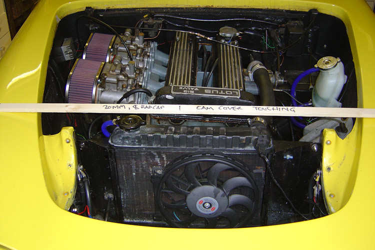
On my Sprint I measured the clearance between cam cover and bonnet with the old chassis before starting any removals. Then fitted the Spyder chassis and found that I needed to put half an inch of packing at the front end, tapering back to nothing at the rear end in order to get things back to where they were. I then decided to add an extra quarter inch at the front, as the rad had occasionally touched the bonnet. These were never precision-made vehicles! 
Don't forget to let the weight of your engine OFF the crane, or jack, before tightening up all the engine mounting bolts!
Best not to take advice from folks who admit they know nothing about fitting a Spyder chassis too.
This shows you what to do next time! The piece of timber was checked for straightness and placed across the tops of the front wings. It was checked for straightness again when the new chassis went in(!)
 ]
]
Don't forget to let the weight of your engine OFF the crane, or jack, before tightening up all the engine mounting bolts!
Best not to take advice from folks who admit they know nothing about fitting a Spyder chassis too.
This shows you what to do next time! The piece of timber was checked for straightness and placed across the tops of the front wings. It was checked for straightness again when the new chassis went in(!)
]Cheers,
Pete.
http://www.petetaylor.org.uk
LOTUS ELAN flickr GROUP: https://www.flickr.com/groups/2515899@N20
flickr: http://www.flickr.com/photos/16096573@N02/sets/72157624226380576/
https://www.flickr.com/photos/16096573@N02/
Pete.
http://www.petetaylor.org.uk
LOTUS ELAN flickr GROUP: https://www.flickr.com/groups/2515899@N20
flickr: http://www.flickr.com/photos/16096573@N02/sets/72157624226380576/
https://www.flickr.com/photos/16096573@N02/
-

elansprint71 - Coveted Fifth Gear
- Posts: 4437
- Joined: 16 Sep 2003

![]() Post by: stugilmour » Sat Oct 16, 2010 4:41 pm
Post by: stugilmour » Sat Oct 16, 2010 4:41 pm
elansprint71 wrote:Then fitted the Spyder chassis and found that I needed to put half an inch of packing at the front end, tapering back to nothing at the rear end in order to get things back to where they were. I then decided to add an extra quarter inch at the front, as the rad had occasionally touched the bonnet. These were never precision-made vehicles!
Pete, pretty much what I found when I recently mounted my Plus 2 on the Spyder chassis.
The mounting points down the backbone define the "ideal level" mounting height of the body.
I required minor packing at the trunk/boot through bolts to prevent putting residual stress into the rear of the body assembly, potentially causing cracking.
I also required ~4 packing washers at the front tabs to prevent fouling, although in my case it was the carb bodies that were the highest point. The front tab packing resulted in one washer on the front spine mounting tab. I cleared the front cam cover with only one washer at the front tabs and no packing of the front spine mounting tab. I still have minor fouling of the carb bodies, which I have temporarily rectified by not fully closing the hood/bonnet; plan to rectify fully by adjustment of the motor mounts over the winter, but will not be moving the body height.
The additional height on the front body and the "slope" in the body mounting do not look visually odd in any way.
HTH
Stu
1969 Plus 2 Federal LHD
1969 Plus 2 Federal LHD
-
stugilmour - Coveted Fifth Gear
- Posts: 2063
- Joined: 03 Sep 2007
![]() Post by: CBUEB1771 » Sun Oct 17, 2010 2:47 am
Post by: CBUEB1771 » Sun Oct 17, 2010 2:47 am
elansprint71 wrote:Best not to take advice from folks who admit they know nothing about fitting a Spyder chassis too.
Good point about that, I forgot that conservation of momentum only applies to Hooke joints in standard Lotus chassis. Perhaps that is why certain posts are prefaced with cautions about experience applied to standard chassis. I'll have to check with Spyder about why their chassis differ so much from Lotus with respect to body mounting.
Russ Newton
Elan +2S (1971)
Elite S2 (1962)
Elan +2S (1971)
Elite S2 (1962)
-
CBUEB1771 - Coveted Fifth Gear
- Posts: 1684
- Joined: 09 Nov 2006
16 posts
• Page 1 of 2 • 1, 2
Total Online:
Users browsing this forum: No registered users and 25 guests