Tripod Racing
25 posts
• Page 2 of 2 • 1, 2
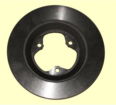
Elan Rear Rotor....
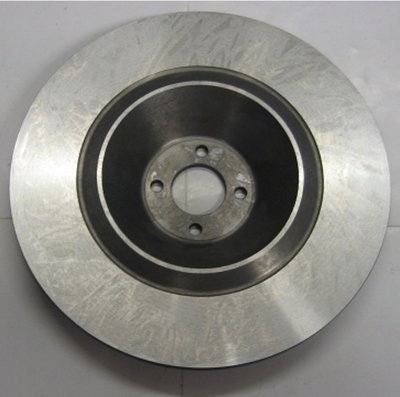
26R Rear Rotor....
Here's the entire assembly.....
The hub and axle are one piece. The rotor fixes to the u-joint yoke and the long bolt goes thru the center of the hub/axle and fixes to the u-joint yoke with a nut.
What's gone is the hub being mounted to the long taper on the outer axle. Worn taper, loose nut or fatigued axle and bye bye wheel and tire.
- lance54
- Second Gear

- Posts: 178
- Joined: 09 Apr 2008
lance54 wrote:Elan Rear Rotor....
26R Rear Rotor....
Here's the entire assembly.....
The hub and axle are one piece. The rotor fixes to the u-joint yoke and the long bolt goes thru the center of the hub/axle and fixes to the u-joint yoke with a nut.
What's gone is the hub being mounted to the long taper on the outer axle. Worn taper, loose nut or fatigued axle and bye bye wheel and tire.
I can see how the axles and coupling all fit together but where is the disk attached?
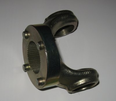
The Kelsport shaft picture earlier in this thread looks to have two dowels projecting on the inner face of the yoke. The 26R disk though has a large centre hole and four fixings. Is there missing part, or are teh brakes inboard?
Ian
68 Elan S4 DHC. Built in a weekend from a kit (just like the advert said)
-

Elanman99 - Fourth Gear

- Posts: 730
- Joined: 11 Sep 2003
I must first acknowledge that I have not used or even seen there parts. I've have only used high strength axle shafts with hubs that fit properly on the taper and not experienced any axle failures with vintage spec tires.
From what I see the assembly is as follows.
The outer u-joint yoke has four pins that engage the rotor.
Between the outer face of the rotor and the inner hub bearing there is a spacer.
A large washer is placed inside the u-joint yoke.
The long bolt seen here goes thru the axle and sandwiches the rotor between the bearing spacer and the u-joint yoke with a suitable nut.
The downside with this assemble is that the long bolt or its retaining nut is now inside the outer u-joint. That might make the final assembly a bit challenging.
The rotor is basically clamped in place and driven by the four pins in the u-joint yoke. Not unlike the rotor attachment on most modern road cars where the rotor floats on the wheel lugs and is clamped in placed by the wheel and lug nuts.
Last edited by lance54 on Fri Jan 13, 2017 4:12 pm, edited 1 time in total.
- lance54
- Second Gear

- Posts: 178
- Joined: 09 Apr 2008
Found a photo of the assembled components.
I wonder how many Elans racing with K/O 26R type wheels are using these parts vs those with a K/O Hub on a standard outer stub axle? The cost of all the above parts is rather alarming.
This set up requires the use of K/O 26R wheels and will set you back 2,055 GBP without the wheels and spinners.
The alternate path to proper K/O 26R wheels is 350 GBP for hubs that fit standard outer stub axles.
Using bolt-on wheels for racing? Better have high strength stub axles and hubs that fit the taper correctly.
- lance54
- Second Gear

- Posts: 178
- Joined: 09 Apr 2008
Clark,
I have been puzzling over this a bit as well. I never realized that the brake discs are located by four dowel pins. I had imagined something more like four bolts going into tapped holes in the yoke. To me the weak point in the design is that the compressive load created by the long, central bolt all seems to be supported by the circlip which establishes the axial location of the inner race of the inboard axle bearing. It does not seem to be a common failure point though. Perhaps some of our readers who run full 26R drive trains will chime in. There have been a couple of questions about FIA acceptance. Lotus homologated all of these parts in period so I don't know why they would not now be accepted by the FIA, Generally speaking TTR does not sell much that is not FIA compliant.
I have been puzzling over this a bit as well. I never realized that the brake discs are located by four dowel pins. I had imagined something more like four bolts going into tapped holes in the yoke. To me the weak point in the design is that the compressive load created by the long, central bolt all seems to be supported by the circlip which establishes the axial location of the inner race of the inboard axle bearing. It does not seem to be a common failure point though. Perhaps some of our readers who run full 26R drive trains will chime in. There have been a couple of questions about FIA acceptance. Lotus homologated all of these parts in period so I don't know why they would not now be accepted by the FIA, Generally speaking TTR does not sell much that is not FIA compliant.
Russ Newton
Elan +2S (1971)
Elite S2 (1962)
Elan +2S (1971)
Elite S2 (1962)
-

CBUEB1771 - Coveted Fifth Gear

- Posts: 1684
- Joined: 09 Nov 2006
Russ,
Good questions.
In this design and in the stock design all the lateral cornering loads (inner and outer) are ultimately absorbed by the bearing snap rings.....true?
Since there are no lateral cornering loads on the brake rotor or the u-joint yoke it would require minimal compression of the thru bolt and nut to secure the hub/axle, rotor and yoke together into one rotating assembly.
Regarding the FIA question I little understanding since it is not a issue on this side of the Atlantic. The idea of racing a wet sump 4 bolt crankshaft engine is not very appealing to me. I did that back in the 1970s and experienced several expensive engine failures....same goes for using a syncro-helical gearbox. Some of these parts can make a car marginally faster but they sure go a long way to improve durability.
- lance54
- Second Gear

- Posts: 178
- Joined: 09 Apr 2008
Clark,
This is where a serious finite element strain analysis could be useful. Cornering loads also put the outboard axle into bending. The resulting deflection of outboard axle, however minute, will likely cause the "fit" of the inner bearing races on the axle and the outer bearing races on the hub carrier both to tighten. The circlips certainly support a lot of the cornering load but probably not all due to minute deflection of the axle in bending. You are correct that the disc and outboard yoke will see little to no axial load due to the sliding spline in the intermediate axle. Therefore there is no need for the central bolt to exert a very large compressive load on the assembly.
This is where a serious finite element strain analysis could be useful. Cornering loads also put the outboard axle into bending. The resulting deflection of outboard axle, however minute, will likely cause the "fit" of the inner bearing races on the axle and the outer bearing races on the hub carrier both to tighten. The circlips certainly support a lot of the cornering load but probably not all due to minute deflection of the axle in bending. You are correct that the disc and outboard yoke will see little to no axial load due to the sliding spline in the intermediate axle. Therefore there is no need for the central bolt to exert a very large compressive load on the assembly.
Russ Newton
Elan +2S (1971)
Elite S2 (1962)
Elan +2S (1971)
Elite S2 (1962)
-

CBUEB1771 - Coveted Fifth Gear

- Posts: 1684
- Joined: 09 Nov 2006
I believe this design is a bit of overkill and very pricey to boot.
Modern high-strength axles and hubs are working fine for me.
Having a rear wheel depart company with your Elan is not pleasant.....an experience I know all too well.
Like this poor chap at the Tour Auto 2000 in 2015:
https://www.youtube.com/watch?v=XgnYIX9PRYc
Modern high-strength axles and hubs are working fine for me.
Having a rear wheel depart company with your Elan is not pleasant.....an experience I know all too well.
Like this poor chap at the Tour Auto 2000 in 2015:
https://www.youtube.com/watch?v=XgnYIX9PRYc
- lance54
- Second Gear

- Posts: 178
- Joined: 09 Apr 2008
lance54 wrote:Like this poor chap at the Tour Auto 2000 in 2015:
https://www.youtube.com/watch?v=XgnYIX9PRYc
Losing two made it a bipod racing ?
S4SE 36/8198
-

nmauduit - Coveted Fifth Gear

- Posts: 2045
- Joined: 02 Sep 2013
25 posts
• Page 2 of 2 • 1, 2
Total Online:
Users browsing this forum: cliveyboy and 18 guests


