Another tacho...
12 posts
• Page 1 of 1
Hi,
I had my RVI tacho converted to RVC when it started to bounce a couple of years ago. It worked fine until last year when something broke. So I had it refurbished again, and I am now reinstalling it. But id does not work when I install and wire as before (no ignition and beam lamps, and no rev counter).
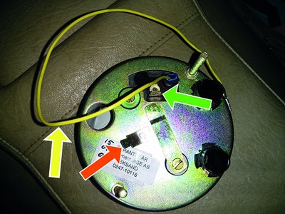
This is how it look?s on the back.
1. What is the yellow wire good for? (have never used it)
2. There are two connections from within the facia: one green/yellow (which I fit over the connector marked with a green arrow in picture), and a black which I fit on the connection marked with a reddish arrow).
3. There is a small black wire from the ignition bulb holder. Is this to be connected to earth?
I have pertronix electric igniton
How do I get this correct?
/Ulf
1974 Lotus Elan +2 130/5
- Uboat
- Second Gear

- Posts: 175
- Joined: 21 Sep 2007
I agree that more information is needed to help you, but as it appears that nothing works the common factor may be a missing or faulty earth connection.
Eric in Burnley
S3SE DHC
Eric in Burnley
S3SE DHC
- ericbushby
- Coveted Fifth Gear

- Posts: 1363
- Joined: 13 Jun 2011
It looks as if the Red arrow points to a tag fastened to the case, so that will be the earth and should connect to one of the various black wires behind the dash.
The Green arrow is prabably the 12volt power feed to the tacho to make its electronics work.
Which mean that the yellow arrow/yellow wire must be the trigger signal wire and needs to go to either the contact-breaker end of the coil or a special output connector of the electronic ignition. If so there is no way this could have worked before without this being connected.
It's possible of course that the functions of the Green-Arrow tag and the Yellow wire are the other way around with the yellow wire being the power feed and the green-arrow tag being the signal wire.
Bill Williams
36/6725 S3 Coupe OGU108E Yellow over Black.
36/6725 S3 Coupe OGU108E Yellow over Black.
- billwill
- Coveted Fifth Gear

- Posts: 5062
- Joined: 19 Apr 2008
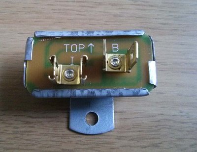
This is the face of my new volt regulator. Can somebode please help me decipher the symbols. What is I and what is B? Which ones delivers 12V?
I was told by the guy who refurbished the tacho (a very senior smiths expert) that it was fine to feed the tacho with 12V current from the voltage stabilizer. Is this correct (RVC plus electric ignition)?
/Ulf
I was told by the guy who refurbished the tacho (a very senior smiths expert) that it was fine to feed the tacho with 12V current from the voltage stabilizer. Is this correct (RVC plus electric ignition)?
/Ulf
1974 Lotus Elan +2 130/5
- Uboat
- Second Gear

- Posts: 175
- Joined: 21 Sep 2007
B - Battery I - Instruments
So B is the un regulated voltage IN and I is the Stabilized 10v
On my S4 there is a 12v Feed from the Ignition going to one side of the B terminal with the other side of the B terminal going to the Tacho, the I on my car only feeds the Fuel gauge but on a +2 you may find it feeds other gauges too.
Note it needs to have a Negative fitted to its Body (Usually grounded via its fixing of the Odometer body)
Chris
-

Grizzly - Coveted Fifth Gear

- Posts: 2023
- Joined: 13 Jun 2010
Uboat wrote:Which ones delivers 12V?
I was told by the guy who refurbished the tacho (a very senior smiths expert) that it was fine to feed the tacho with 12V current from the voltage stabilizer. Is this correct (RVC plus electric ignition)?
/Ulf
The voltage stabilizer's output is 10 volts.
Phil Harrison
1972 Elan Sprint 0260K
1972 Elan Sprint 0260K
-

pharriso - Coveted Fifth Gear

- Posts: 3606
- Joined: 15 Sep 2010
Uboat wrote:This is the face of my new volt regulator. Can somebode please help me decipher the symbols. What is I and what is B? Which ones delivers 12V?
I was told by the guy who refurbished the tacho (a very senior smiths expert) that it was fine to feed the tacho with 12V current from the voltage stabilizer. Is this correct (RVC plus electric ignition)?
/Ulf
>Which ones delivers 12V?
Neither! One terminal CONSUMES 12V and delivers an average 10 volts at the other terminal. With a modern electronic regulator the output is a steady 10 volts, with the older bimetalic type the output is a series of 12 volt pulses which AVERAGE down to 10 volts.
>I was told by the guy who refurbished the tacho (a very senior smiths expert) that it was fine to feed the tacho with 12V current from the voltage stabilizer
I bet he didn't say exactly that, he probably said,
1. it was fine to feed the tacho FROM THE 12V TERMINAL OF the voltage stabilizer
or
2. it was fine to feed the tacho FROM THE 12V INPUT OF the voltage stabilizer
It may seem nitpicking, but things are much easier if you actually understand what the bits do.
Bill Williams
36/6725 S3 Coupe OGU108E Yellow over Black.
36/6725 S3 Coupe OGU108E Yellow over Black.
- billwill
- Coveted Fifth Gear

- Posts: 5062
- Joined: 19 Apr 2008
OK, I understand it is 10V, thanks
I now discovered that this new voltage stabilizer is different from the old stabilizer in that the old stabilizer have female B terminals and male I terminals. So I unintentionally connected the ignition switch wire to the I terminal and the tacho and fuel gauges to the B terminals. Is the ok?
Also, how do I tell which of the coil's terminal is negative?
1974 Lotus Elan +2 130/5
- Uboat
- Second Gear

- Posts: 175
- Joined: 21 Sep 2007
Well over-complicating this, there is nothing special about the 12v feed to the Stabilizer so just use the second terminal on the 12v side as instructed by the +2 wiring diagram if you want to supply 12v to the Tacho.
-VE on the coil is the one with - stamped onto it failing that the White wire from the Ignition switch is +ve and the -ve is the trigger from the Distributor.
-VE on the coil is the one with - stamped onto it
Chris
-

Grizzly - Coveted Fifth Gear

- Posts: 2023
- Joined: 13 Jun 2010
So I tried every combination of wiring, and I still have no function. Apparently the tacho gets current as ignition lamp works fine. However, could not check the high beam lamp function as lamps suddenly will not pop up (worked fine a day ago).This is so Lotus...
Is the headlamp switch be connected to the tacho, somehow?
I double-checked the coil and wiring is correct. Is there a way to check that pulses from the coil-wire (from negative) are ok?, with a multimeter?
/Ulf
Is the headlamp switch be connected to the tacho, somehow?
I double-checked the coil and wiring is correct. Is there a way to check that pulses from the coil-wire (from negative) are ok?, with a multimeter?
/Ulf
1974 Lotus Elan +2 130/5
- Uboat
- Second Gear

- Posts: 175
- Joined: 21 Sep 2007
12 posts
• Page 1 of 1
Total Online:
Users browsing this forum: No registered users and 28 guests


