Plus 2 Heater Overhaul
42 posts
• Page 2 of 3 • 1, 2, 3
Brilliant idea for the rotary switch and the various resistors! Loads of fan speeds instead of two!
Keep us posted if you try it.
Regards
Jeff 72+2
Keep us posted if you try it.
Regards
Jeff 72+2
-

jeff jackson - Fourth Gear

- Posts: 578
- Joined: 31 May 2004
graham wrote:Interested to know which wires attach to which terminals to get 2 speeds as 1 terminal has 2 spade connectors
graham
The high speed wire from the switch connects to the double terminal on the resistor.
The power wire from the fan motor connects to the double terminal on the resistor.
The low speed wire from the switch connects to the single terminal on the resistor.
The ground wire from the fan motor connects to ground.
On the 'high' switch setting the power to the motor by-passes the resistor thru the double terminal.
On the 'low' switch setting the power to the motor goes thru the resistor (resistor in series with motor).
Have left out wire colours as they may vary by model of Plus 2.
Although you are replacing resistor so maybe not an issue for you, I found the stock resistor can ground to the heater box causing it to be energized. Added insulation to the resistor mount to avoid problem.
HTH
Stu
1969 Plus 2 Federal LHD
1969 Plus 2 Federal LHD
-

stugilmour - Coveted Fifth Gear

- Posts: 2063
- Joined: 03 Sep 2007
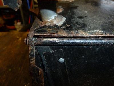
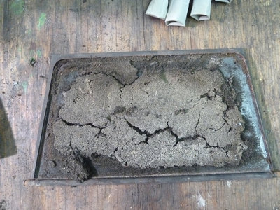
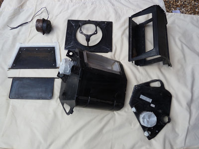
I have started taking the heater apart. At first I was only going to undo the self tappers on the non-flap lever side and clean it up. As ever, further investigation uncovered rust and general filth so in the end I bit the bullet and drilled out all the pop rivets and now it down to nearly all its component parts. I've got two problems, at the moment:
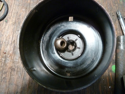
1. I can't get the fan of the shaft. I wanted to oil the bearings and check the brushes. Does anyone know how to undo the retaing clip without ruining it and therefore making unusable again and not breaking the plastic fan. A picture of the clip is below.
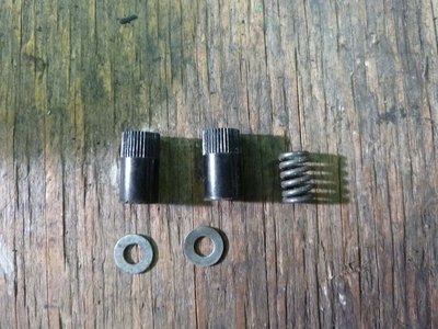
2. As I could get the fan off I decided to split the motor to see if the back came off and then I could withdrawn the heater through the fixing plate as the retaining lugs prevented this. In splitting the motor I found some components inside that I didn't spot where they came from. Theres a picture below. I'd be grateful if anyone has taken a motor apart and knows where the bits go. Thanks
- gwiz22
- Second Gear

- Posts: 98
- Joined: 29 Oct 2005
Hi Graham
Hope all goes well with the heater rebuild. As you have the heater out and soon to put it back I wonder if U could measure the distance from the heater to the rear of the dashboard in the area of the central block of the 4 fuses. That would help me in planning my rebuilt wiring loom would be useful.
cheers
Bob
- bob_rich
- Fourth Gear

- Posts: 564
- Joined: 06 Aug 2009
Bob,
I will be pleased to measure this distance for you. At the moment, I have the heater in bits. In the end, I drilled out all the pop rivets as the inside had rusty bits. I plan to paint all the bits and reassemble over the next few days. However, it might be some time before I re-fit the dashboard, as I'm painting the engine bay and all the components that normally sit in there have been removed. So the dash won't go back till they have all been replaced. Maybe a few weeks. Would that be ok?
Regards
Graham
- gwiz22
- Second Gear

- Posts: 98
- Joined: 29 Oct 2005
Hi Gerry
thanks 4 the suggestion The "loom manufacturer" is replying 2 your post!!
Being in electronics I quite enjoy the electrical side of cars and the reason for my interest in the depth behind the dash board fuse bank is that I am reviewing the fusing and looking at adding a larger bank of modern style blade fuses while still retaining the original fuse cover. Info on the depth is thus important to ensure I pick the correct fuse holders and installation method.
I agree that the use of flag 1/4" terminals will be both neater and give me a bit more space
Graham sorry 2 slightly hi jack your post! whenever you get a measurement that will B fine gen is always useful. regarding your motor I dont recognise the parts in your pictures. Smiths motors are quite easy to get and usually easy to repair and so a similar motor should be available from BMC Mini or similar vintage sources. If U get really stuck I can strip down one of my spare motors and photograph it 4 U.
Thanks both 4 comments and info
cheers
bob
- bob_rich
- Fourth Gear

- Posts: 564
- Joined: 06 Aug 2009
Bob. Thanks for the reply from the Loom manufacturer! and designer!
I'm presuming you are using relays to switch most loads and avoid voltage drops on lights/cooling fan motor etc. What are you using for voltage spike protection? Varistors by any chance? Littlelfuse?
I'm presuming you are using relays to switch most loads and avoid voltage drops on lights/cooling fan motor etc. What are you using for voltage spike protection? Varistors by any chance? Littlelfuse?
- gerrym
- Fourth Gear

- Posts: 894
- Joined: 25 Jun 2006
Hi All,
This morning I just put the old dashboard on to make some rough measurement for replacing the heater unit with A/C evaporator unit. Attached please find the measurement without the heater, hope this help.
Ennio
Hong Kong (33 deg C today)
This morning I just put the old dashboard on to make some rough measurement for replacing the heater unit with A/C evaporator unit. Attached please find the measurement without the heater, hope this help.
Ennio
Hong Kong (33 deg C today)
- ennio
- First Gear

- Posts: 16
- Joined: 01 Mar 2010
Hi graham
Still in the design stage 4 the loom. I will use relays mainly to support the ignition switch because quite a lot of current can go through its contacts so ignition switch will only handle modest currents. For suppresion will diode clamp them so that the coil voltage will be minimised at at turn off. There is the horn relay and vacuum pod for headlamps of course and I may fit a relay for the rear screen heater as that is quite a hefty load. Am going 2 diode clamp all these relays 2 minimise noise as I will be fitting an ECU and want 2 keep transients 2 a minimum. Fuel pump and ECU power relays will also be diode clamped. will fit external diodes at all the relay terminals crimped into the 1/4" terminals with the wires.
Hi Ennio
Thanks for an excellent sketch! will be able to get a good idea of clearance to the fuses from that. I suppose where U R a heater is rather unnecessary so good idea 2 change 2 air con!
thanks both for info and help
cheers
Bob
- bob_rich
- Fourth Gear

- Posts: 564
- Joined: 06 Aug 2009
Bob,
It looks like the response from Ennio is far better than I could have hoped to achieve. Accordingly, I shall stand down from this task.
For those of you who expressed an interest in following my heater overhaul, here?s the story so far:
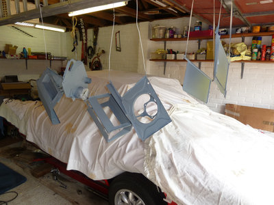
The initial plan was to just replace the foam on the flaps. After removing one side of the heater, I could see a fair bit of rust inside the casing. So I drilled out all the pop rivets and in the end took the whole thing apart. The foam simply disintegrated and I found that white spirit easily cleaned the residue glue off the flaps. So jenolite on the rusty bits and quick rub down and they were ready for painting.
I managed to separate the fan from the motor shaft by supporting the fan with a couple of long spanners supported by a couple of blocks of wood and driving off the shaft with a suitable size punch. With the fan off it should have been a simple case of removing the two halves of the motor casing. However the front half casing simply would not come off the end of the shaft. There was about 4mm protruding and it simply would not go any furhter. Following my success with the hammer and punch on the fan, I decided these useful tools should be applied again.
WARNING ? DO NOT USE A HAMMER AND PUNCH TO REMOVE THE FRONT HOUSING OF A HEATER MOTOR.
What had happened is that the end of the shaft had got a little rusty. Hardly noticeable at all. However, it was enough stop the shaft sliding free of the bush. My hammering forced the bush out of the claw type retaining ring and there is no way of getting it back in. (see picture). The sad thing was a little rib with emery cloth on the shaft and the bush slides up and down it perfectly. So lesson learned. I?ve bought another motor of ebay for a 60s Land Rover. So I hope Bob was right and most cars of that era shared the same motor. I will take this one apart carefully and note where all the internal parts are located and therefore I will know where to fit the parts that fell out when I took the motor apart as mentioned in my earlier post.
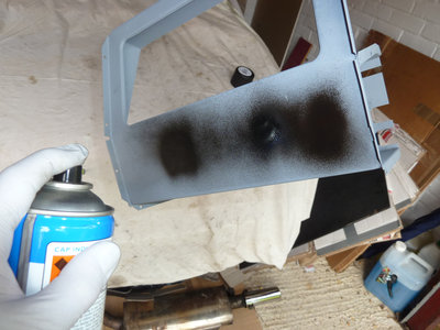
The parts are all now in primer and I started finishing them in satin black tonight. I will let the paint harden for a couple of days and hopefully get the unit back together at the weekend.
Regards
Graham
- gwiz22
- Second Gear

- Posts: 98
- Joined: 29 Oct 2005
Graham,
you're either luckier or more careful than I was, I broke the fan on my spare heater trying to take it off the shaft!
Mike
you're either luckier or more careful than I was, I broke the fan on my spare heater trying to take it off the shaft!
Mike
- mikealdren
- Coveted Fifth Gear

- Posts: 1224
- Joined: 26 Aug 2006
Mike,
I think the trick is to support the fan either side of the shaft, close to the shaft. I mentioned it in my earlier post. A couple of strips of stiff metal would do the trick, I used some long spanners. With these abutted either side of the shaft, then position on top of a couple of large pieces of wood, so the motor is clear to drop as you drive out the shaft from the fan. I have to say that it was more of a tap than a drive, so I'm hoping there is enough spring tightness in the clip on the fan to hold on to the shaft when I put it back together again. I keep my fingers crossed.
BTW, where are you in Surrey? I'm in Bisley.
Regards
Graham
- gwiz22
- Second Gear

- Posts: 98
- Joined: 29 Oct 2005
42 posts
• Page 2 of 3 • 1, 2, 3
Total Online:
Users browsing this forum: No registered users and 15 guests

.jpg)
