+2 Boot/trunk interior
55 posts
• Page 3 of 4 • 1, 2, 3, 4
Marty:
Do indeed wish you could come see my car and it's boot but alas it is in Surrey (BC, Canada). And, the car is a February 1970 Plus 2S. So no rectangular hole cut out of the floor board for battery (though I assume there are great similarities nonetheless).
And not that my car is a perfect and shining example; I would commend it's boot to anyone for examination because it came to me in virtually complete and original factory form. The only thing non-original was just one of the two boot floorboards. So it was easy for me to disassemble, document, refurbish and reinstall everything. And it works great, in it's factory-original design.
So . . . I do commend to you a visit to someone with a factory original/stock arrangement, so you can take from that the measurements, et cetera. Even if it means a bit of a journey.
Sorry I can't be of any more help than that. If push came to shove, I would be willing to send you all my boot documentation pix from my car's restoration process, FWIW.
Regards, Randy
-

Sea Ranch - Coveted Fifth Gear

- Posts: 1141
- Joined: 07 Mar 2011
martynw wrote:I've done a sketch of the cross section of the boot showing how where I think the brackets should be fitted, after reading this thread. The car is the later model with the cable operated boot, so does not have the central support in the centre of the rear bulkhead. Just wondered if anyone could explain.
- Does the top of the rear bulkhead board tuck under the reinforcing angle for the boot opening mechanism (at A) or is it fixed to the face of this angle somehow? Does the rear board sit or fix directly on the bracket (B) or does the floorboard sit on that bracket with the rear bulkhead on top of it? Should the rear bulkhead be fitted tight to the rear of the car bodyshell, between the mouldings for the light fittings, or fitted further forward attached to the rear of these mouldings (where there are some suspicious looking holes)?
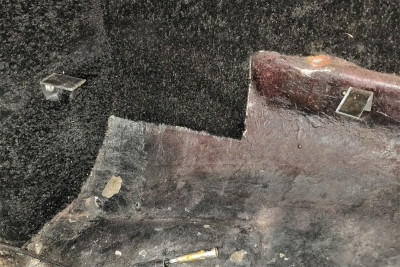
The rear bulkhead board sits just forward of the reinforcing angle (A in your drawing). It's carpeted, with the carpet glued to the board. If you look at the carpet PDF posted above (Section BF -- Body - Carpet), you'll see that that piece (20F) shows a right angle section of carpet on the top edge. That right angle section is glued to the top side of the reinforcing angle (A), forming sort of a hinge and attachment for the bulkhead board. You'll see that the bulkhead board has a cutout that matches the floor support at the bottom of the bulkhead. The carpeted bulkhead panel sits tight to the back of bracket. That supplies the vertical orientation of the bulkhead. The floor boards sit in front of the bulkhead and directly on the bracket. You can't have the bulkhead panels sitting on top of the floor boards anywhere or you can't get them out.
Here are a couple of pics that may help.
First the support isn't held in place by bumper bolts. They're 1/2 inch, 1/4 x28's I believe. They're shown in the parts book. These are installed and sealed before attaching the bumper.
martynw wrote:- Does the petrol tank board sit directly on the bracket (C) YES or do the floorboards go fully into the bracket with the petrol tank board sitting on top of them? No Does the petrol tank board sit vertically, or the parallel to the rear of the petrol tank (and if so, what holds it there)? I assume this board slots up forward of the rear scuttle brace that attaches to the rear wheel arch, does it lean back on it, or is it held in better than that?
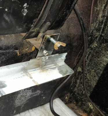
There are two mounting holes in the tank board and they line up with the holes shown in this pic.I can't put hands on either the panel or the mounting bracket right now to show how that works. The pic shows one side the other side is a mirror image of this side. The other two holes on each side are the mounting points for the front floor bracket.
martynw wrote:- If possible, could someone measure up some rough dimensions for the space between the brackets at A and C, and the space length these brackets protrude from the bumper bolts and fixing straps respectively. I'll be making these up, so keen to get them close to originals.
I'll try to get some measurements later today.
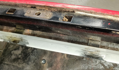
martynw wrote:- Finally, where do the floor boards sit in relation to the small ledges on the sides of the rear wings formed by the moulded bumper recess? Sitting on them, above them or below?
See pics
Last edited by Bud English on Sun Mar 10, 2024 6:32 pm, edited 1 time in total.
Bud
1970 +2S Fed 0053N
"Winnemucca - says it all really!!"
1970 +2S Fed 0053N
"Winnemucca - says it all really!!"
- Bud English
- Coveted Fifth Gear

- Posts: 1081
- Joined: 05 Nov 2011
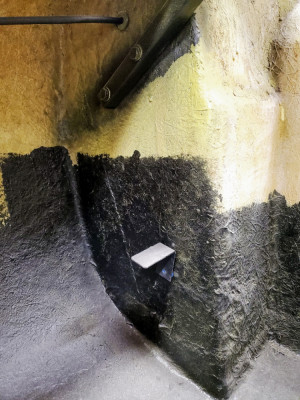
When I started into my rebuild, the trunk was the best preserved part, fortunately and unfortunately. 
Bud
1970 +2S Fed 0053N
"Winnemucca - says it all really!!"
1970 +2S Fed 0053N
"Winnemucca - says it all really!!"
- Bud English
- Coveted Fifth Gear

- Posts: 1081
- Joined: 05 Nov 2011
Bud - those pics are fantastic and a real help thank you.
I've seem to have something of a mishmash of brackets and fixings - I'm not sure the images of the boot board fixings are quite what mine had originally (or at least has now) as I have the u-shaped brackets shown back on page 2 of this thread (Sun Aug 18, 2013 2:20 am). I don't have the captive bolts/threaded stud shown in that picture but I can work out a way of fixing something along those lines.
Initially, I the floor brackets I had were (badly) shown below fixed to these u-shaped brackets, see below.
At the rear bulkead, the floorboards sat on flat pieces of steel bolted onto the bumper bolts that protruded no more than 1/2" from the rear bulkhead. This meant the boards were so deep they were a real pig to get in and out - even after you had removed the petrol tank and rear panels which were sat on top of them.
Today I knocked up a longer bracket that links the two you see on the petrol tank bracket above. I also made a similar length one to attach to the bumper bolts for the rear bulkhead, but this was before I saw what you had said (and shown) about the originals being wider and having their own bolts. I'll work what to do about this tomorrow - may be easiest just to weld in an extension). My rear bracket now all welded as one piece, but it matches your photo in that the flat section the floor panels sit on is at the same level as the top of long arms of the bracket that bolts on under the bumper moulding, so should be OK.
What still puzzles me is getting the distance right between the rear bulkhead and petrol tank brackets. I haven't drilled the rear one yet, but I was intending to mark it up and drill it so that it had 634mm between the the two brackets. I'd arrived at that dimension as it would take the 610mm board (according to the CAD diagram on page 1 of this thread) plus 12mm for the each of the petrol tank and rear bulkhead boards.
Added to that I have a slight worry about the height of my petrol tank bracket, as it looks higher than that shown in the photos on page 2. It wouldn't be difficult to could weld some vertical pieces on and drop down a bit though.
All the photos of the side brackets and those on the wheel well are really useful - none of those are present at the moment, but easy to make up and final fit can be worked out when the two largest brackets are in place. I also get the rear panel carpet hinge idea - the reinforcing angle was so clean on my car it hadn't occurred to me it may once have had glue on it. Do you know how wide the carpet cut out is for the locking mechanism? Just around the fitting bolted at the centre, or should I keep the two square holes open as well?
Many thanks again - I'll add some pics of what I made when I am next in the workshop (may not get there tomorrow but definitely will on Thursday).
- martynw
- First Gear

- Posts: 38
- Joined: 27 Mar 2014
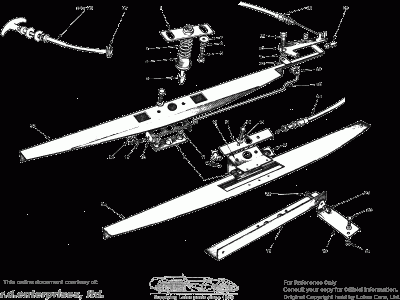
This GIF, from the parts manual Section BE -- Body - Boot, shows those rear supports (19) and the bracket (18). Click on the GIF and it will enlarge and show black on white.
If you need dimensions for those, they're easy to get. With the dimensions and what you can see above, they'd be pretty easy to make. They are 16GA mild steel like the reinforcing angle (34). When I installed mine I added a short length of square tubing under the right side of the bracket. It is riveted to the bracket and sits on the top surface of the muffler bulge for added support. You can see the rivet heads in the photo.
The brackets in your photo do look like they would be too high as shown, but that's easy to correct when you've determined the height of the boot floor boards. You asked for the distance from the top of A to the "L" of the bracket. That's 7&1/8" on my car.
You may be able to tell where those side and wheel wheel brackets go by locating the rivet holes in the body or at least the position if they've been filled in. The holes and rivets for the side brackets are behind and hidden by the bumper when it's installed. The rivets going into the wheel well are hidden by undercoating. Be sure to seal all the rivets and bolts passing through the body to prevent leaks.
I noticed in some of the pictures in this thread that those brackets are shown attached over the top of the felt and carpet. Mine were not. They were riveted to the body and slits had been cut in the felt and carpets to go over them.
Bud
1970 +2S Fed 0053N
"Winnemucca - says it all really!!"
1970 +2S Fed 0053N
"Winnemucca - says it all really!!"
- Bud English
- Coveted Fifth Gear

- Posts: 1081
- Joined: 05 Nov 2011
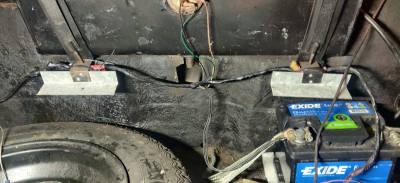
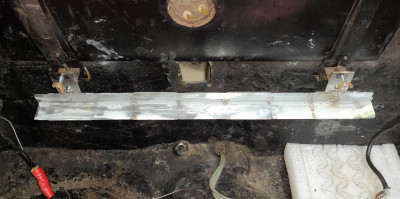
Boot is mostly there now. I made new front and rear brackets up as well as the L-shaped ones that fit to the rear wing and wheel arch and have cut out a fuel tank board and floor boards. I've done the fuel tank one in 9mm ply, which sounds thicker than the original, but I had it handy. Floor is in 10mm, roughly to the shape in the CAD diagram in this thread - though I found it ended up about 10mm wider than the diagram, so presumably it is closer fitting than the original into the wings.
So here is how it now is, in case anyone else finds it useful.
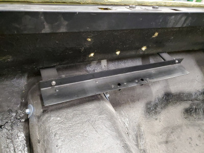
Fuel tank bracket - bolted to the U-bracket on the tank straps, with an extension above and a bolt welded through to create a stud to hold the fuel tank board.
Rear bracket, made in one piece and a compromise between what was there (brackets fitted to the inside two bumper bolts) and what should be there (brackets fitted to two separate bolts). Each side now bolts to one bumper bolt and an new bolt one I drilled through to fit. Ignore the hole in the bracket on LHS of photo - this angle used to be a fluorescent light, and that is where the starter fitted. I think this counts as "upcycling".
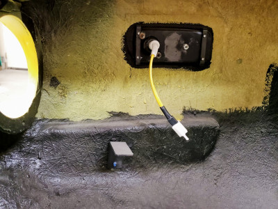
L-brackets on wheel arch/wing. Bolted on top of carpet as that was already glued in place and not worth removing.
- martynw
- First Gear

- Posts: 38
- Joined: 27 Mar 2014
Final query is on the rear board. I think I got the wrong end of the stick with these, as all boards in my car had been made in 12mm ply. I suspect the rear one was originally just 2-3mm fibreboard with carpet glued on.
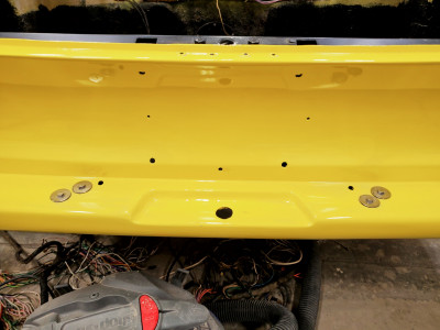
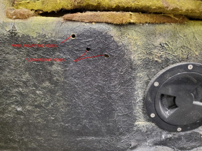
What I'm still not clear on is how far to the sides this board should be. I assume it must have stopped short of the the fittings for the lamp bulbs, as they project into the boot. The previous owner had cut and carpeted a 12mm board that wedged between the mouldings for the rear lamps (you can see the dark brown board in the photo below).
My current plan would be to cut the board along the green line and glue on an oversize piece of carpet so the excess loosely covers the lamp fittings. I don't know if the hole that looks like it once took a self tapper (marked with white arrow) is also part of this, or if it just relied on the glued carpet "hinge" from the reinforcing angle and being held back the floorboards.
However if anyone knows the original is different let me know and I can tweak this.
- martynw
- First Gear

- Posts: 38
- Joined: 27 Mar 2014
You are correct. It was a fiberboard panel. I kept my original for a pattern. I'll dig it out later this morning and get some photos and add dimensions.
Bud
1970 +2S Fed 0053N
"Winnemucca - says it all really!!"
1970 +2S Fed 0053N
"Winnemucca - says it all really!!"
- Bud English
- Coveted Fifth Gear

- Posts: 1081
- Joined: 05 Nov 2011
I am sure mine is original, and is screwed into the top edge of the base where the boot lid meets. It is thin steel angle iron, and the 2-3 carpet covered fibreboard.
What is important is the width, it is a apress fit between the insides below the tail lights. I can flip out the bottom, and have access to licence plate fixings without too much struggle. A light push holds it, and the base holds it with light pressure from the front (by the fuel tank).
What is important is the width, it is a apress fit between the insides below the tail lights. I can flip out the bottom, and have access to licence plate fixings without too much struggle. A light push holds it, and the base holds it with light pressure from the front (by the fuel tank).
Born, and brought home from the hospital (no seat belt (wtf)) in a baby!
Find out where the limits are, and start from there
Love your Mother
Earth
Find out where the limits are, and start from there
Love your Mother
Earth
-

h20hamelan - Coveted Fifth Gear

- Posts: 1960
- Joined: 25 Sep 2010
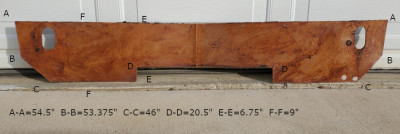
Here are the dimensions of the board.
It's not clear in the photo, but A-A, B-B, and C-C are straight edges and parallel to each other. B-B is 5.25"" below A-A. If you divide the horizontal dimensions in half and measure from the middle you will get the angles needed at the ends. Clear as mud?
I think that H20 is correct. There may have been a thin sheet metal angle stiffener at the top edge of the board. You can see holes along that top edge and two holes by the light access holes where the panel attaches to the rear fiberglass. It's been about ten years since I took this thing apart.
Bud
1970 +2S Fed 0053N
"Winnemucca - says it all really!!"
1970 +2S Fed 0053N
"Winnemucca - says it all really!!"
- Bud English
- Coveted Fifth Gear

- Posts: 1081
- Joined: 05 Nov 2011
You're quite welcome. It's good to be able to help someone after all the help I've received here. 
Bud
1970 +2S Fed 0053N
"Winnemucca - says it all really!!"
1970 +2S Fed 0053N
"Winnemucca - says it all really!!"
- Bud English
- Coveted Fifth Gear

- Posts: 1081
- Joined: 05 Nov 2011
Great info on here, just finished fitting a new boot floor. I had the originals which were badly warped and chopped about but were a reasonable template for the new floor panels which I made from 9mm ply so a little stiffer than the originals. The rear of the car seemed to bow out making it difficult to close the boot lid, to I fabricated a rear boot panel that attached to the boot catch plate and incorporated a 1” square tube right across the boot attaching to the rear light body mouldings. This tube was joined by an ally sheet riveted to it and also to the rear boot floor support angle. When tightening up the boot handle securing screws this pulled the whole rear of the car firmly into line so that the boot lid shut easily and lined up nicely with the rear of the car.
Just got to make the petrol tank cover board now, so have one question. How is the top of this board secured? I have the original lower mounting angle strip which appears to have three holes for self tapping screw holes in it to secure it. There is a small length of angle strip attached to the underside of the rear parcel shelf, does the board test against this, tuck behind it or what. It has some screw holes in it but no idea how you could get to put any screws in at the top.
Just got to make the petrol tank cover board now, so have one question. How is the top of this board secured? I have the original lower mounting angle strip which appears to have three holes for self tapping screw holes in it to secure it. There is a small length of angle strip attached to the underside of the rear parcel shelf, does the board test against this, tuck behind it or what. It has some screw holes in it but no idea how you could get to put any screws in at the top.
Change is inevitable, except from a vending machine!
- Bigbaldybloke
- Fourth Gear

- Posts: 894
- Joined: 16 May 2017
55 posts
• Page 3 of 4 • 1, 2, 3, 4
Total Online:
Users browsing this forum: No registered users and 25 guests

