+2 Boot/trunk interior
55 posts
• Page 2 of 4 • 1, 2, 3, 4
Floor Boards.
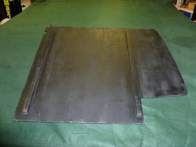
RH Boot Floor (underside).
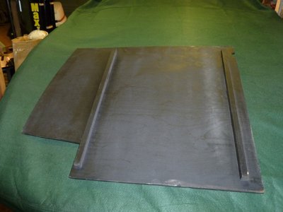
All battens Length 21 1/2" x 11/16" x 11/16"
LH Boot Floor (underside)
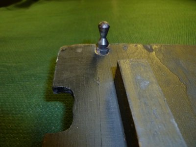
Boot Floor retention peg. Pushes into the holes on the rear bracket which has a retention clip.
See previous post.
RH Boot Floor (underside).
All battens Length 21 1/2" x 11/16" x 11/16"
LH Boot Floor (underside)
Boot Floor retention peg. Pushes into the holes on the rear bracket which has a retention clip.
See previous post.
Trevor
1968 Elan +2 50/0173
1968 Elan +2 50/0173
-

TeeJay - Fourth Gear

- Posts: 579
- Joined: 30 May 2007
Here are a few photo's.
In some of the other posted pics you can see the 'L' shaped bracket attached with the side bumper bolt.
I will see if I have a better pic showing attachment of the rear support. In stock form the attachment to the fibreglass at the rear of the car is pretty lousy. I used blocks of wood fibreglassed in place to provide solid support for this bracket. I think the stock arrangement was just a couple of screws, and they kept pulling out. Before installing the bracket, seal the holes for the licence plate lights with Dum Dum; it is a bit difficult to get your hand in there with the bracket in place.
HTH
- Attachments
-

- This is my bulkhead (photo taken from the back side). It shows the cut out for the fuel filler elbow. You can see the foam and carpet cut a bit larger than the plywood (the original piece was fibreboard). You can also see the carpet left loose over the cutout to cover the filler elbow. There are two holes drilled at the base of the bulkhead to hold it in place to the bolts screwed in thru the captive nuts on the fuel hold down straps. The other screws and stuff on the back of the board are non-stock; they are holding a pouch on the face of the bulkhead. The little strap tabs are also non-stock, they make it a bit easier to remove the bulkhead.
-

- Boot floor showing battens around perimeter of the plywood floor piece. I did not put in the cutout for the tail light assembly (shown in the dimensional drawing), which is probably a mistake. It can be a bit tight to insert the floor pieces with the bulkhead piece over the gas tank installed. The batten down the middle is attached to the right floor piece, and acts as a support for the left floor piece.
Stu
1969 Plus 2 Federal LHD
1969 Plus 2 Federal LHD
-

stugilmour - Coveted Fifth Gear

- Posts: 2063
- Joined: 03 Sep 2007
Great topic and pics! 
A couple of other points for folks with stripped boots or with old destroyed carpet & felt. Mine were too far gone to use as templates and came off in chunks.
Pre-cut soundproofing pieces are available from Sue Miller if you need them. Note shipping can be a bit of an issue if you are getting a complete set for the car as it ended up being a couple of boxes of felts. I believe she has precut and dressed carpet sets available as well; I sourced my carpet in NA instead.
There are soundproofing felt pieces glued to the sides of the boot. You can sort of see the outline of the felt in one of the pictures above. They also have carpet over top glued to the felt and fibreglass. There are a few pieces of felt on the fibreglass boot floor as well.
In stock form there was also a fibreboard piece on the rear bulkhead over the tail light assembly. I left this piece out when I rebuilt things. I found it was OK to just glue the carpet to the felt and attach the carpet up by the boot latch with screws (this was the stock method of attaching the carpet). The flexible felt and carpet covers the tail light assembly fine without the fibreboard piece.
Looking at Trevor's pic above of the hold downs, I see I did mine a bit incorrectly. I think the idea is to attach the hold down permanently to the floor boards and use the ball shaped clip to hold the thing in place. I put wing nuts on the studs and sort of left the clips in place. This works if you don't have those clip pieces or the rear mount. I guess I can change mine back to stock.
IIRC my stock floor boards (assume they were stock) had a finger hole drilled in them to ease removal of the piece. I think they were about 1/2" holes at the back of the trunk near the hold down clips. Looks like I didn't bother to put them in my replacement floor boards.
HTH
Stu
1969 Plus 2 Federal LHD
1969 Plus 2 Federal LHD
-

stugilmour - Coveted Fifth Gear

- Posts: 2063
- Joined: 03 Sep 2007
This is great stuff and very helpful. I have downloaded all the pics and will be comparing them to mine. I don't have the L brackets installed on mine, so that explains why the boards kept sagging. I've also never seen these 'ball' clips before, which explains why they kept sliding about. Where can I get these clips from or what are called so I can trawl the interweb?
As for the bulkhead board, the stock fitting it simply 2 bolts at the bottom from the fuel tank straps?
- Ian
As for the bulkhead board, the stock fitting it simply 2 bolts at the bottom from the fuel tank straps?
- Ian
-

Iyarno - Second Gear

- Posts: 155
- Joined: 21 Aug 2010
Ian, here is a picture of the mounting bolt (one side, there is one on each strap).
The ball clip things are a bit unusual, so can't help with a source. Perhaps you could get all the pieces from a parts car. If you have to fabricate the back bracket with angle iron you could just use wing nuts to hold the floor pieces down?
HTH
The ball clip things are a bit unusual, so can't help with a source. Perhaps you could get all the pieces from a parts car. If you have to fabricate the back bracket with angle iron you could just use wing nuts to hold the floor pieces down?
HTH
- Attachments
-
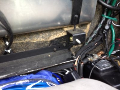
- This is the bulkhead mount. There is a captive nut behind the 'U' shaped black bracket. There is a bolt (with a 7/16" head IIRC) threaded in from the back side of the bracket to form a threaded stud. A hole in the bulkhead holds it in place with a fender washer over the carpet and a Nyloc nut. The two bolts are all that is needed to hold the bulkhead in place. The stud configuration makes it easier to install the bulkhead; it would be very dificult to thread a bolt into the captive nut while holding the bulkhead in position and your head bumping into the boot lid.
Stu
1969 Plus 2 Federal LHD
1969 Plus 2 Federal LHD
-

stugilmour - Coveted Fifth Gear

- Posts: 2063
- Joined: 03 Sep 2007
Having taken a look a my boot layout I now suspect there are differences between early +2's with transverse exhausts and +2S's onwards with straight exhausts.
I have an early car, which has no sign of the U shaped bracket on each side of the fuel straps. Instead there are 2 small screw/mini bolt holes each side. I assume the bulkhead board attaches directly to this? The U shaped bracket in the photo appears to sit lower than mine, which is inkeeping with the later cars having a larger and deeper boot.
Does this seem to make sense?
I also have 2 pin holes along the rear bracket between the lights. I guess this is where the pins need to be positioned on the base boards.
-

Iyarno - Second Gear

- Posts: 155
- Joined: 21 Aug 2010
Ian, that's interesting.
Can't help with the fuel tank bracket part. maybe shoot Mark (Elan in the Forest) a quick PM to look at the thread. I believe he has worked with several early cars and might be able to enlighten us.
The tail light bracket holes look the same. Is there a spring clip on the bottom side of the bracket? I think I can see one?
Best of luck with the project.
Stu
1969 Plus 2 Federal LHD
1969 Plus 2 Federal LHD
-

stugilmour - Coveted Fifth Gear

- Posts: 2063
- Joined: 03 Sep 2007
Ian.
Mine is an early +2 (1968) with a transverse exhaust and also does not have the U shaped bracket.
My photos are not the best as my body is still separated from the rolling chassis and is on the 2 post lift.
To get in focus I put the rear flood light on, but where that shines into the boot I get the black felt / carpet looking brownish. I have changed the camera setting white balance, so hopefully better.
Anyway back to the topic.
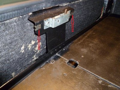
My board by the fuel tank is attached by screws in the holes highlight below.
The Rear board is attached with screws going into U clips as below.
Re my camera skills. See below re white balance setting how it improves the black boot floor.
You can also see how the "finger holes" work to lift the floor boot up. (Still got to find the other "post" and fix it to the LH floor board.
I am still working on the boot.
I purchased a roll of felt and cut the shapes for both the cabin and boot. Now all glued in.
The carpets for cabin and boot I purchased as sets made up by Sue Miller and to date have only fitted 4 items in the boot.
i.e. Fuel Tank board, Rear board and the 2 boot corners so that I could bolt on the Scuttle support brace and as per the previous photos the 2 L shaped boot floor support brackets.
Trevor
1968 Elan +2 50/0173
1968 Elan +2 50/0173
-

TeeJay - Fourth Gear

- Posts: 579
- Joined: 30 May 2007
Trevor, the photos and PDFs are fantastic. Thanks so much for posting them.
I think I have most parts as they should be, however the metal(?) L shaped pieces which attach to the left and right wheel arches on mine are just wooden blocks. Have you got any photos of yours as I need to try and make something up here. I also need to make up a backboard to cover the fuel tank. Would you be able to provide dimensions so I can cross reference them with my own measurements.
- Ian
-

Iyarno - Second Gear

- Posts: 155
- Joined: 21 Aug 2010
Hi Ian,
The measurements were on my post of Friday Aug 16th and are typically under the photo.
I think that the backboard to cover the fuel tank is OK, I called it the Fuel tank board.
ie
Measurements:-
Long Length (bottom) = 41 1/2". Short Length (top) = 38 1/2". Height = 12". Cut out = 8" x 3"
The Long Length rests on the Boot Floor support bracket- Fuel Tank.
The previous photos of the L brackets were not good so here are some more.
Measurements:- Length = 2". Height = 7/8". Width = 1". Thk = 0.079"
The 2" Length sticks outwards on to which the boot floor rests.
Also note that the short length 7/8" is positioned downwards.
The photo is of the LH side, but the RH side is the same. Note both brackets are at a mid point across the fixing area. Hope this makes sense?
And one with the boot floor and carpet in position.
If you have any questions, then please fire away.
Tomorrow when I have a little more time, I will post PDF's of the Felt and Carpet items.
Trevor
1968 Elan +2 50/0173
1968 Elan +2 50/0173
-

TeeJay - Fourth Gear

- Posts: 579
- Joined: 30 May 2007
Trevor, a few more questions...I've just noticed you're running felt all over the boot floor. Is this normal? Does the spare wheel sit on top of the felt or is there a cutout? Does the felt here get carpeted or have a protected layer on top of it?
Thanks for all the other info. I'll be working on it mine soon. Looks like you're almost there.
Ian
Thanks for all the other info. I'll be working on it mine soon. Looks like you're almost there.
Ian
-

Iyarno - Second Gear

- Posts: 155
- Joined: 21 Aug 2010
Ian.
Regarding the Felt.
If you look at the "Felt Detail" PDF below, you will see that items 43 has a cut out for the wheel, you also incude item 44. My choice (for improved noise insulation and that I have the transverse exhaust) was to put in item 38 and other felt to completely cover the boot floor, including the raised section for the transverse exhaust.
So my spare wheel will go on top of the felt.
With reference to the carpet.
No the carpet does not cover the felt on the boot floor, only the boot sides. See my next post for details.
I've had to do the 2 posts as my Adobe for some reason will no longer save single pages. So I have to copy each page across to MS Word and then save as a PDF. I will sort this out later.
Trevor
1968 Elan +2 50/0173
1968 Elan +2 50/0173
-

TeeJay - Fourth Gear

- Posts: 579
- Joined: 30 May 2007
Ian
As per my previous post, the carpet does not cover the boot floor. It covers the wings and the boards for the fuel tank and rear of the boot.
With reference to the Carpet Details PDF.
Items 16 & 17 go top to bottom. These are the carpets I have glued and have the L brackets and Scuttle support brace bolted on.
Item 21 is the carpet for Board that covers the fuel tank.
Item 20 is the carpet for the board that cover the rear of the boot with the cut out for the boot latch.
Item 22 covers the wooden floor boards.
Items 18 & 19 cover the wings almost down to the boot floor.
I have not glued these in my car yet as they cover a bolt hole for the rear bumper. I need to decide whether to have the original bumper re chromed or buy a new one. Probably go with re chrome now as we are near the end of August and accept the delays.
Best of luck
Trevor
1968 Elan +2 50/0173
1968 Elan +2 50/0173
-

TeeJay - Fourth Gear

- Posts: 579
- Joined: 30 May 2007
I know this is reviving an old thread, but there is so much useful information and photos here already, it seems a better to keep any new information in the same place.
I'm trying to sort my boot boards out now, currently the car has a random selection of home made brackets and boards, which neither fit that well or look like anything on this thread. So I think it makes sense to try and get back to something close to the original.
Key problem I have is that measured from front to back, my floor boards are almost 3 inches longer than the CAD drawing earlier in this thread (670mm vs 610mm). This makes them very difficult get in, and they must be fitted before the petrol tank board or the rear board, both of which then sit on top of them.
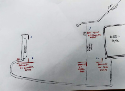
I've done a sketch of the cross section of the boot showing how where I think the brackets should be fitted, after reading this thread. The car is the later model with the cable operated boot, so does not have the central support in the centre of the rear bulkhead. Just wondered if anyone could explain
- Does the top of the rear bulkhead board tuck under the reinforcing angle for the boot opening mechanism (at A) or is it fixed to the face of this angle somehow? Does the rear board sit or fix directly on the bracket (B) or does the floorboard sit on that bracket with the rear bulkhead on top of it? Should the rear bulkhead be fitted tight to the rear of the car bodyshell, between the mouldings for the light fittings, or fitted further forward attached to the rear of these mouldings (where there are some suspicious looking holes)?
- Does the petrol tank board sit directly on the bracket (C) or do the floorboards go fully into the bracket with the petrol tank board sitting on top of them? Does the petrol tank board sit vertically, or the parallel to the rear of the petrol tank (and if so, what holds it there)? I assume this board slots up forward of the rear scuttle brace that attaches to the rear wheel arch, does it lean back on it, or is it held in better than that?
- If possible, could someone measure up some rough dimensions for the space between the brackets at A and C, and the space length these brackets protrude from the bumper bolts and fixing straps respectively. I'll be making these up, so keen to get them close to originals.
- Finally, where do the floor boards sit in relation to the small ledges on the sides of the rear wings formed by the moulded bumper recess? Sitting on them, above them or below?
I realise there are quite a few questions so many thanks in advance. Do wish it was easier to go somewhere and have a look at one done properly, but sadly can't see that happening for a while yet....
- martynw
- First Gear

- Posts: 38
- Joined: 27 Mar 2014
55 posts
• Page 2 of 4 • 1, 2, 3, 4
Total Online:
Users browsing this forum: h20hamelan and 24 guests

