Keinzle clock protection circuit & PCB
20 posts
• Page 2 of 2 • 1, 2
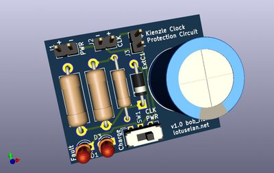
I've been playing with the board layout a bit (can't leave it alone!). I reduced the size, removed three of the capacitors and added the option to mount the (now, single 4700uF) capacitor remotely so you can reduce the board size to save space if you need to.
To remote mount the capacitor, you need to cut the board where indicated (on the underside) and connect the capacitor to J3, being mindful of the polarity. With judicious shaving, it could be made to fit into the tiny enclosure I mentioned earlier, but I'd recommend wiring flying leads to the jumper pads in order to connect to the car's loom and clock rather than soldering spade connectors to it (which I think can't be made to fit the enclosure, anyway; plus, I'm concerned about the reliability of my prototype board).
If you want to build one of these clock protectors, you can get the boards for $8.95 for three from OSHPark: https://oshpark.com/shared_projects/Pw9dLIxB.
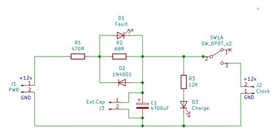
The schematic with matching annotations:
Big thanks to Bob for dreaming it up!
-

JonB - Coveted Fifth Gear

- Posts: 2399
- Joined: 14 Nov 2017
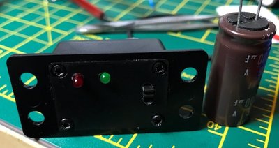
Here's a picture of the finished module.
[Edit: I've tested it and the red LED seems to be bright now. Also, it flashes when the clock's solenoid is activated, nice. On a short, it flashes then goes dim. But I seem to have broken it slightly, as it is winding for 48 seconds irrespective of the capacitor size.]
[Edit: I've tested it and the red LED seems to be bright now. Also, it flashes when the clock's solenoid is activated, nice. On a short, it flashes then goes dim. But I seem to have broken it slightly, as it is winding for 48 seconds irrespective of the capacitor size.]
-

JonB - Coveted Fifth Gear

- Posts: 2399
- Joined: 14 Nov 2017
I read the solenoid needs a 1A kick to energise properly. So you?ll need a pretty hefty battery (comparatively speaking) to do this, and it needs to be 12v so it?ll be bigger than the capacitor. However, you will lose the protection, because it won?t discharge in one hit, so if there?s a short or stuck contacts, your solenoid is still going to burn out.
On the other hand, the capacitor discharges in one shot, more or less, then recharges gradually while the clock is ticking through the last wind. If the car?s battery discharges, or there is a short in the clock, the 470R plus 68R resistors limit the current so much that the coil is protected. It?s all explained in the document.
Plus this circuit is proven (by Bob).
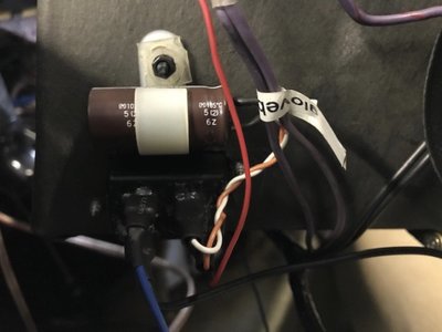
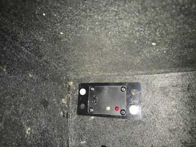
Incidentally, here?s a picture of it on the inside of the glove box.
It?s very discrete, but I need to get some black screws to secure it.
-

JonB - Coveted Fifth Gear

- Posts: 2399
- Joined: 14 Nov 2017
20 posts
• Page 2 of 2 • 1, 2
Total Online:
Users browsing this forum: No registered users and 11 guests

